Process Building Models
< Previous section Next section >
Group Building Points into Clumps
We will group building points into clumps by density-based spatial clustering:
Tool: Density-based Spatial Clustering Geoprocessing → LIS Pro 3D → Segmentation // Tools → LIS Pro 3D → Segmentation
| Parameter | Setting |
|---|---|
| Data Objects | |
| Point Clouds | |
| >> Point Cloud | las_subset_tiles |
| Attribute 1 | X |
| Attribute 2 | Y |
| Attribute 3 | Z |
| Constraint | <not set> |
| < Point Cloud | <not set> |
| Options | |
| Copy existing attributes | 🗹 |
| Attribute Suffix | bld |
| Region Growing | |
| Dimension | 3-dimensional |
| Search Radius | 2 |
| Minimum Number of Points | 15 |
| Constraint | |
| Cluster | |
| Cluster Size | ☐ |
| Filter by Cluster Size | 🗹 |
| Minimum Cluster Size | 200 |
- Provide the building point cloud las_subset_tiles in the Point Cloud section
- Set an Attribute Suffix (in order to give the generated identifier a unique name): bld
- Set the Search Radius to 2m
- Set the Minimum Number of Points to 15
- Check the Filter by Cluster Size checkbox
- Set the Minimum Cluster Size to 200 points
- Click Execute
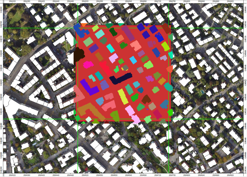
This will group the points into spatial clusters (clumps). The point cloud now has a new attribute that indicates the unique identifier of each clump called cluster_bld. Below, the clumps are visualized by a randomly selected color:
Find Planar Roof Segments in the Point Clouds
Now we will find roof segments in the point cloud via clump segmentation:
Tool: Clump Segmentation
Geoprocessing → LIS Pro 3D → Segmentation // Tools → LIS Pro 3D → Segmentation
| Parameter | Setting |
|---|---|
| Data Objects | |
| Point Clouds | |
| >> Point Cloud | las_subset_tiles |
| Clump ID | cluster_bld |
| Seed Attribute | <not set> |
| Threshold Attribute | <not set> |
| Direction Scanner (X) | <not set> |
| < Point Cloud Segmented | <not set> |
| Options | |
| Copy existing attributes | 🗹 |
| Attribute Suffix | roof |
| Segmentation | |
| Tile Size | 10 |
| Overlap | 5 |
| Minimum Segment Size | 20 |
| Distance Threshold | 0.15 |
| Model Point Distances | 0.02;2 |
| Slope Range | 0;90 |
| Iterations | 50 |
| Seed | 2 |
| Region Growing | |
| Radius | 0.75 |
| Minimum Segment Size | 20 |
| Maximum Angle Normals | 10 |
| Maximum Plane Offset | 0.5 |
| Filter Segments | ☐ |
| Output | |
| Segment Size | 🗹 |
| Normal Vector | ☐ |
- Provide the building point cloud in the Point Cloud section
- Provide the previously generated cluster_bld as the Clump ID
- Set an Attribute Suffix (in order to give the generated identifier a unique name): “roof”
- Set the Overlap to 5m
- Set the Distance Threshold to 0.15m
- Set the Radius to 0.75
- Check the Segment Size checkbox
- Click Execute
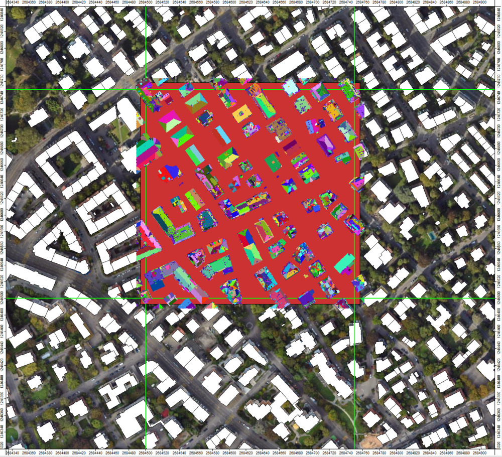
This will extract planar patches in the building point cloud and will attach a unique segmentid_roof to the attributes table of the point cloud. Note how roof segments can now be differentiated in the dataset:
Calculate Slope of Planar Patches
Use the tool: LIS Pro 3D > Analysis > Segment Features
Tool: Segment Features
Geoprocessing → LIS Pro 3D → Analysis → Features // Tools → LIS Pro 3D → Analysis
| Parameter | Setting |
|---|---|
| Data Objects | |
| Point Clouds | |
| >> Point Cloud | las_subset_tiles |
| Segment ID | segmentid_roof |
| Direction Scanner (X) | <not set> |
| Copy existing attributes | 🗹 |
| < Point Cloud Features | <not set> |
| Attribute Suffix | roof |
| Options | |
| … | … |
| Local Plane Features | |
| Normal Vector | ☐ |
| Slope | 🗹 |
| Aspect | ☐ |
| Distance (absolute) | ☐ |
| Distance (signed) | ☐ |
| Deviation | ☐ |
| Standard Deviation | ☐ |
| … | … |
- Provide the building point cloud in the Point Cloud section
- Provide the previously generated segmentid_roof as the Segment ID
- Set an Attribute Suffix (in order to give the generated identifier a unique name): “roof”
- Check Slope checkbox
- Click Execute
This will generate a slope_roof attribute.
Filter Out Steep and Small Segments
Now, our point cloud could still include segments that are either too small (non-major roof parts) or too steep (likely not part of a roof) which we will filter out:
Tool: Attribute Filter
Geoprocessing → LIS Pro 3D → Filtering → Point Cloud // Tools → LIS Pro 3D → Filtering
| Parameter | Setting |
|---|---|
| Data Objects | |
| Point Clouds | |
| >> Point Cloud | las_subset_tiles |
| Attribute 1 | segmentsize_roof |
| Attribute 2 | slope_roof |
| Attribute 3 | <not set> |
| Copy existing attributes | 🗹 |
| < Point Cloud | <create> |
| Options | |
| Method | drop points |
| Attribute 1 | |
| Filter Type | lower limit (min) |
| Minimum | 50 |
| Attribute 2 | |
| Filter Type | upper limit (max) |
| Maximum | 85 |
| Attribute 3 |
- Provide the building point cloud in the Point Cloud section
- Provide the previously generated segmentsize_rood as Attribute 1
- Provide the previously generated slope_roof as Attribute 2
- Set the output Point Cloud to <create>
- Choose Method “drop points”
- Choose Filter Type for Attribute 1 (here segmentsize_roof): lower limit (min)
- Set Minimum to 50 points
- Choose Filter Type for Attribute 2 (here slope_roof): upper limit (max)
- Set Maximum to 85 degree
- Click Execute
Setting the output point cloud to <create> generates a new point cloud instead of modifying the input. This ensures the original (unfiltered) point cloud remains unchanged.
After running the tool, a new point cloud las_subset_tiles_filtered will appear in the data tab.
View the Filtered Point Cloud in 3D
Tool: Point Cloud Editor
Geoprocessing → LIS Pro 3D → Point Cloud Editor // Tools → LIS Pro 3D → Point Cloud Editor
| Parameter | Setting |
|---|---|
| Data Objects | |
| Point Clouds | |
| >> Point Cloud | las_subset_tiles_filtered |
| Intensity | intensity |
| RGB | <not set> |
| Shading | <not set> |
| Classification | classification |
| Random | segmentid_roof |
| Normal Vector (X) | <not set> |
| Report Attribute 1 | <not set> |
| Report Attribute 2 | <not set> |
| Grids | |
| > Elevation Grids | No objects |
| > Color Grids | No objects |
| Shapes | |
| > Shapes | <not set> |
| Options | |
| Work on Copy of Point Cloud | ☐ |
| Background Color | Black |
| Classification LUT | ASPRS LAS (Formats 6-10) |
- Provide the filtered point cloud in the Point Cloud section
- Provide the intensity attribute in the Intensity section
- Provide the classification attribute in the Classification section
- Provide the csegmentid_roof attribute in the Random section
- Click Execute
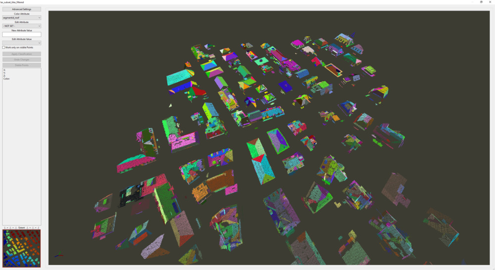
Type Q on the keyboard to switch to segment coloring. Here we can inspect the planar patches of the point cloud that could be extracted:
Close the Point Cloud Editor to continue.
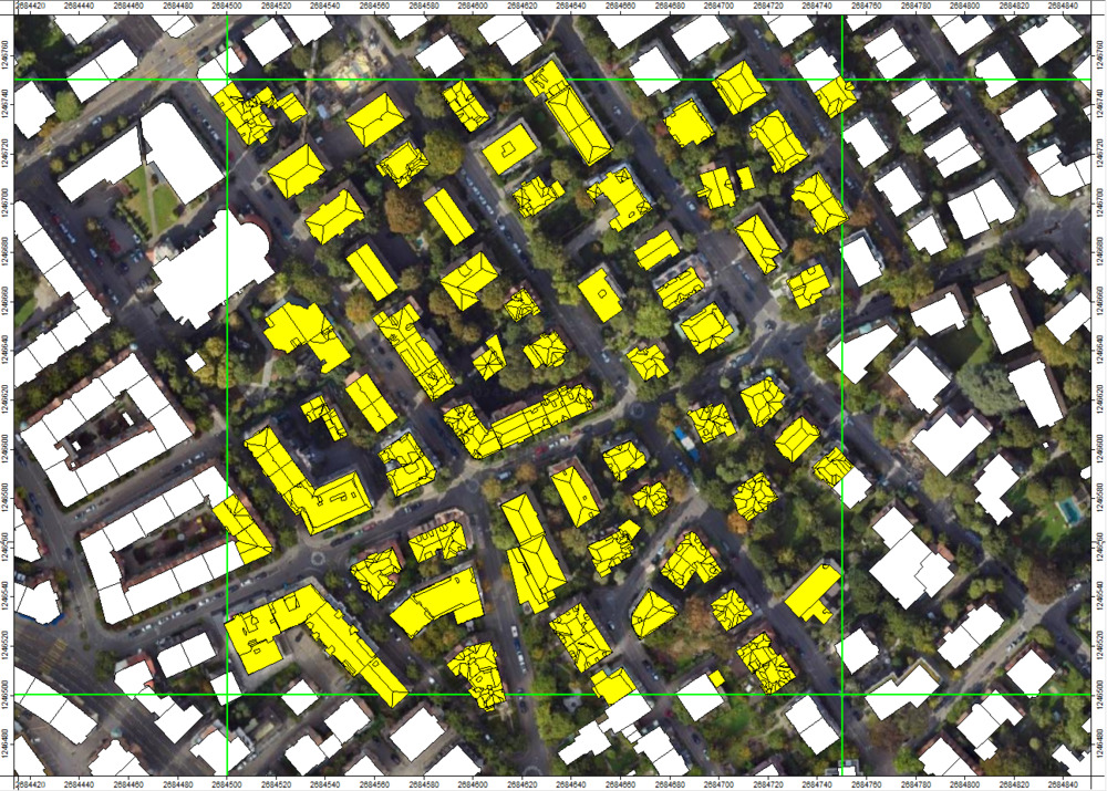
Assign Roof Segments to Buildings
Now we want to assign the prepared point cloud data to the given building footprints (extracted in the previous tutorial)
Tool: Assign Roof Segments to Buildings
Geoprocessing → LIS Pro 3D → City Modeller // Tools → LIS Pro 3D → City Modeller
| Parameter | Setting |
|---|---|
| Data Objects | |
| Point Clouds | |
| >> Point Cloud | las_subset_tiles_filtered |
| Roof Identifier | segmentid_roof |
| Blocked Segment | <not set> |
| Copy existing Attributes | 🗹 |
| < Point Cloud | <not set> |
| Attribute Suffix | |
| Shapes | |
| >> Building Polygons | Building_Footprints_Selection [Selection] |
| Building Identifier | proc_id |
| Labelling Flag | <not set> |
| Options | |
| Minimum Percentage Inside | 10 |
| Point Coverage Filter | ☐ |
| Flag Used Segments | ☐ |
| Remove Unconnected Segments | ☐ |
| Identifier Undefined Points | -1 |
- Provide the filtered building point cloud in the Point Cloud section
- Provide the previously generated segmentid_roof as the Roof Identifier section
- Provide the building footprints, selected for this processing unit, in the Building Polygons section
- Provide the attribute proc_id in the Building Indentifier section
- Click Execute
Note that you can also generate your own building footprints directly from the point cloud data. In this case you would need to run the following tool before Assign Roof Segments to Buildings
Tool: LOD0/1 Building Modeller
Geoprocessing → LIS Pro 3D → City Modeller // Tools → LIS Pro 3D → City Modeller
Add the filtered point cloud to the map
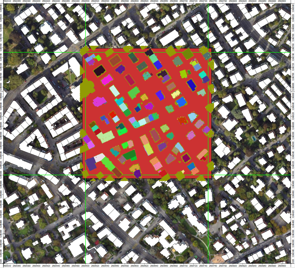
You can see that the proc_id (the unique building identifier) was attached to the filtered point cloud
Additionally, a new attribute segmentid_roof_relabel has been introduced. In this attribute, segments that occupy only a very small percentage of their respective building are marked as invalid
Generate Building Models
Now we will generate LOD2 building models for the selected building footprints:
Tool: LOD2 Building Modeller
Geoprocessing → LIS Pro 3D → City Modeller // Tools → LIS Pro 3D → City Modeller
| Parameter | Setting |
|---|---|
| Data Objects | |
| Point Clouds | |
| >> Point Cloud | las_subset_tiles_filtered |
| Building ID | proc_id |
| Roof ID | segmentid_roof_relabel |
| Grids | |
| Grid system | 0.25; 1092x, 1103y; 2684489…x 1246488…y |
| >> DTM | tiles |
| Shapes | |
| >> Ground Plan | Building_Footprints_Selection [Selection] |
| Building ID | proc_id |
| Bed-Plate Offset | <not set> |
| << LOD2 Models | <create> |
| Options | |
| Maximum Roof Slope | 85 |
| Minimum Point Count Roof | 20 |
| Maximum Edge Length | 1.5 |
| Maximum Distance To Line | 0.3 |
| Snapping Distance | 0.75 |
| Method Gap Filling | roof plane minimum height |
| Iterations Roof Gaps | 5 |
| Minimum Building Height | 0.1 |
| Rectify Small Polygons | 🗹 |
| Maximum Area | 2 |
- Provide the filtered building point cloud in the Point Cloud section
- Provide the previously generated proc_id in the Building ID section
- Select the Grid System (the only available one)
- Provide the tiles grid in the DTM section
- Provide the building footprints Building_Footprints_Selection [Selection] (the ones selected for this tile), in the Ground Plan section
- Provide the attribute proc_id in the Building ID section
- Set the Maximum Roof Shape value to 85 degree
- Set the Minimum Point Count Roof value to 20 points
- Click Execute
Load the output building models to the map.
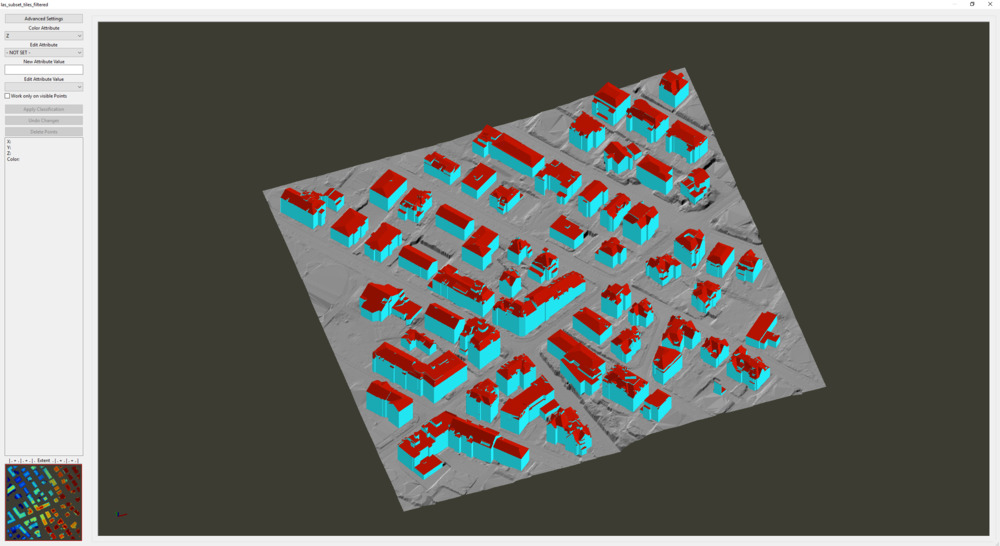
View the Generated LOD2 Building Models in 3D
Tool: Point Cloud Editor
Geoprocessing → LIS Pro 3D → Point Cloud Editor // Tools → LIS Pro 3D → Point Cloud Editor
| Parameter | Setting |
|---|---|
| Data Objects | |
| Point Clouds | |
| >> Point Cloud | las_subset_tiles_filtered |
| Intensity | intensity |
| RGB | <not set> |
| Shading | <not set> |
| Classification | <not set> |
| Random | <not set> |
| Normal Vector (X) | <not set> |
| Report Attribute 1 | <not set> |
| Report Attribute 2 | <not set> |
| Grids | |
| > Elevation Grids | 1 object (tiles) |
| > Color Grids | 1 object (tiles.Hillshade) |
| Shapes | |
| > Shapes | las_subset_tiles_filtered_LOD2 |
| Color | surfaceClass |
| Continue Digitizing | ☐ |
| Options | |
| Work on Copy of Point Cloud | ☐ |
| Background Color | Black |
- Provide the filtered point cloud in the Point Cloud section
- Provide the tiles layer in the Elevation Grids section
- Provide the tiles.hillshade layer in the Color Grids section
- Provide the LOD2 model in the Shapes section
- Provide the surfaceClass attribute in the Color section of the Shapes section
- Click Execute
Visualization tips: - Type W on the keyboard to switch the shapes rendering style from Wireframe to Face (and back) - Increase/decrease point cloud transparency with F11/F12
Close the Point Cloud Editor to continue.
Inspect Building Model Attributes
If we select the LOD2 Model in the Data Tab, we can inspect its properties in the Description Tab of the Properties Window
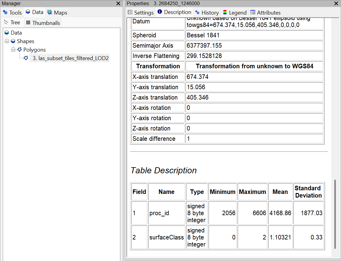
The output has 2 Attributes:
- The unique identifier for processing (proc_id)
- The surfaceClass which corresponds to Ground, Wall or Roof encoded as 0, 1, 2 (see table below)
- previous versions of LIS Pro 3D also included the LOD level (LOD) as a third attribute - this is no longer the case in recent versions
| surfaceClass ID | corresponding class |
|---|---|
| 0 | Ground |
| 1 | Wall |
| 2 | Roof |
You can select and filter specific parts of buildings (e.g., roofs only) by selecting the corresponding surfaceClass using Shapes > Tools > Select by Attributes …
Calculate Building Statistics
In order to further enrich the building-level information, we can calculate statistics for each building:
Tool: LOD2 Building Statistics
Geoprocessing → LIS Pro 3D → City Modeller // Tools → LIS Pro 3D → City Modeller
| Parameter | Setting |
|---|---|
| Data Objects | |
| Shapes | |
| >> Building Models | las_subset_tiles_filtered_LOD2 |
| Building ID | proc_id |
| Surface Class | surfaceClass |
| < Building Model Statistics | <create> |
| Grids | |
| Grid system | 0.25; 1092x, 1103y; 2684489…x 1246488…y |
| > DTM | tiles |
- Provide the LOD2 model in the Building Models section
- Provide the proc_id attribute in the Building ID section
- Provide the surfaceClass attribute in the Surface Class section
- Provide the tiles layer in the Grid System > DTM section
- Click Execute
This creates a new las_subset_tiles_filtered_LOD2_stats layer
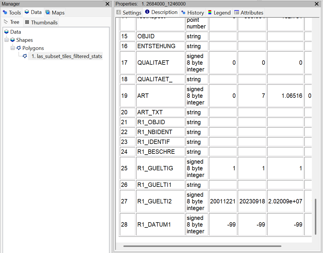
This layer includes additional attributes 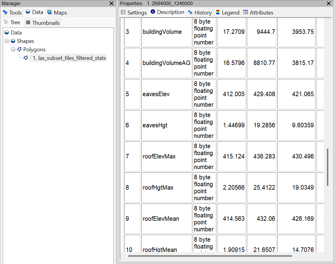
Join Attributes from Input Building Footprint Layer
Now we will attach (join) the building statistics directly to our building footprints:
Tool: Join Attributes from a Table
Geoprocessing → Table → Tools;Shapes → Attributes // Tools → Table → Tools
| Parameter | Setting |
|---|---|
| Data Objects | |
| Tables | |
| >> Input Table | las_subset_tiles_filtered_LOD2_stats |
| Input Join Field | proc_id |
| >> Join Table | Building_Footprints_Selection [Selection] |
| Join Table Field | proc_id |
| Add All Fields | 🗹 |
| < Unjoined Records | <not set> |
| Shapes | |
| < Result | <not set> |
| Options | |
| Keep All | 🗹 |
| Case Sensitive String Comparison | 🗹 |
- Provide the LOD2 model with statistics in the Input Table section
- Set the Input Join Field to proc_id
- Provide the input Building Footprints in the Join Table section
- Set the Join Table Field to proc_id
- Click Execute
Now we have also the input attributes available for the final output building model:
Export
Create a new folder output. Now export the building models to CityJSON:
CityJSON
Tool: Export Shapes to CityJSON
Geoprocessing → LIS Pro 3D → City Modeller // Tools → LIS Pro 3D → City Modeller
| Parameter | Setting |
|---|---|
| Data Objects | |
| Shapes | |
| >> City Objects | las_subset_tiles_filtered_LOD2_stats |
| Object ID | proc_id |
| Surface Class | surfaceClass |
| Measured Height | measuredHeight |
| External Reference ID | OBJID |
| Generic Attributes (City Object) | 7 |
| Generic Attributes (Polygon Face) | 12,13 |
| Tables | |
| > Address Table | <not set> |
| Options | |
| Output File | C:\\…\output\Building_Model_Tutorial.json |
| CityJSON Version | 2.0.1 |
| City Object | Building |
| Level of Detail | 2 |
| EPSG Code | 2056 |
| Reference Date | 2024-07-09 |
| External Reference as … | Information System |
| Information System External Reference | OBJID |
| Geometry Type | Solid |
| Clean Vertices | 🗹 |
| Snapping Tolerance | 0.001 |
| Coordinate Precision | 3 |
| UUID Generation | UUID v4 |
- Provide the building model dataset with all attributes attached in the City Objects section
- Provide proc_id as Object ID
- Provide surfaceClass as Surface Class
- Provide measuredHeight as Measured Height
- Provide slope and aspect as Generic Attributes (Polygon Facade) - these will be attached to the individual polygons of a building
- Provide roofHgtMax as Generic Attributes (City Object) - this will be attached at the building level
- Provide OBJID as External Reference ID
- Define an output file in your output folder
- Set the correct EPSG Code
- Set the correct Reference Date
- Set OBJID as the Information System External Reference
- Click Execute
CityGML
Tool: Export Shapes to CityGML
Geoprocessing → LIS Pro 3D → City Modeller // Tools → LIS Pro 3D → City Modeller
| Parameter | Setting |
|---|---|
| Data Objects | |
| Shapes | |
| >> City Objects | las_subset_tiles_filtered_LOD2_stats |
| Object ID | proc_id |
| Object Part | <not set> |
| Surface Class | surfaceClass |
| Surface Group | <not set> |
| Measured Height | measuredHeight |
| External Reference ID | OBJID |
| Generic Attributes (City Object) | 7 |
| Generic Attributes (Polygon Face) | 12,13 |
| Tables | |
| > Address Table | <not set> |
| Options | |
| Output File | C:\\…\output\Building_Model_Tutorial.json |
| City Object | Building |
| Level of Detail | 2 |
| Creation Date | 2024-07-09 |
| EPSG Code | 2056 |
| External Reference as … | Information System |
| Information System | OBJID |
| Geometry Type | Solid |
| Coordinate Precision | 3 |
| UUID Generation | UUID v4 |
| Attach Textures | ☐ |
- Provide the building model dataset with all attributes attached in the City Objects section
- Provide proc_id as Object ID
- Provide surfaceClass as Surface Class
- Provide measuredHeight as Measured Height
- Provide OBJID as External Reference ID
- Provide slope and aspect as Generic Attributes (Polygon Facade) - these will be attached to the individual polygons of a building
- Provide roofHgtMax as Generic Attributes (City Object) - this will be attached at the building level
- Define an output file in your output folder
- Set the correct Reference Date
- Set the correct EPSG Code
- Set OBJID as the Information System External Reference
- Click Execute